
Disclaimer:
The company I'm working for1 makes industrial machines to cut leather, and a lot of other stuff fabric-related.
There is this new machine which has cameras and uses AI to recognize imperfections in the tissues, in order to automatically avoid cutting pieces which would not pass the minimum quality standards. But this is not an article about AI, or fashion industry supply chain: this is an article about cameras.
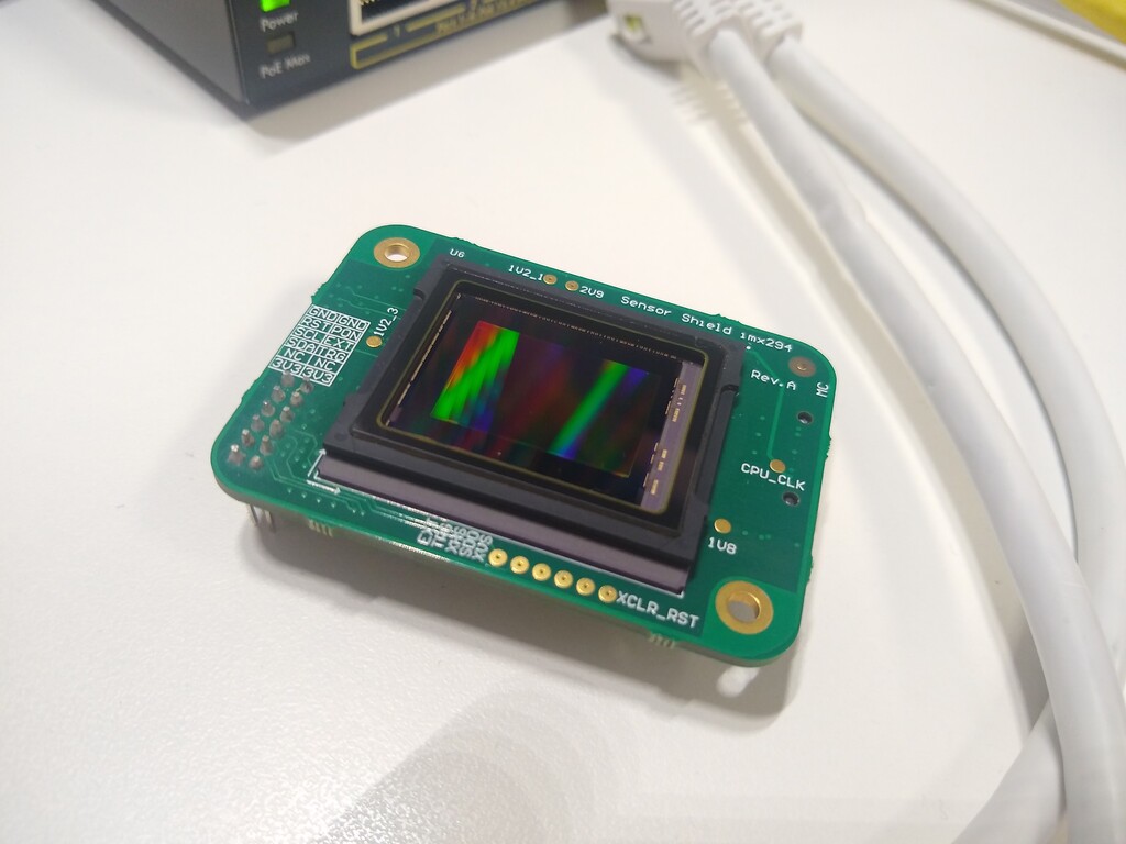
The new camera is an IMX-8 Linux-based SOC, with a MIPI interface, and has a Sony IMX294 sensor.
The Sony IMX294 is a 12Mp, 4:3 sensor, which is also famous and suited for astronomy, because of its "big" pixels which capture a lot of light with low noise.
I was given the task of writing the device driver for the IMX294, and I was very
lucky, because
will127534
had already done 90% of the job for me (albeit for a different platform)
and I only had a very - very - vague idea of how the V4L2 subsystem works.
Thank you will127534, you are (one of) my heroes.
But unfortunately, the IMX294 is also a "fast" sensor, compared to the industrial background we are used to. So we had to tame it a bit, before we could use it with our SOC.
We already had an IMX-8 industrial-graded SOC that we used in a previous version of the camera, with our Linux BSP, applications, et cetera. The IMX-8 has a MIPI peripheral, which, as every hardware device in this wonderful world, has its own special quirks and unique bugs.
For example, it has a limited 256-pixel RX FIFO which hangs the peripheral
when overrun. (ERR050384 and similar)
So, higher resolution images (which have lines up to ~4000 pixels long)
often caused random freezes, which needed a power cycle to be fixed.
(actually, the peripheral starved the CPU sending a gazillion of FIFO overrun interrupts per second).
Blocking cameras are not life-threatening (in our context), but still,
customers usually don't like this sort of things.
I played a bit with the various pixel/ui/sys internal clocks, and I also randomly attended a MIPI talk at Fosdem earlier this year, just to be sure to avoid missing some important pieces, since I (used to) know almost nothing about image sensors.
But in the end, despite the producer keeping its industrial secrets, I had to hack a bit with the opaque, undocumented, IMX294 PLL registers, which let me run the sensor at 804 MHz, instead of the standard 1728 MHz of the bus.
I agree with you, that's a bold move and an odd frequency, but this magic number has been chosen because of engineering rule number one: it just works ™.
We didn't have a > GHz oscilloscope to exactly check the MIPI clock signal, but our handful-hundreds-of-megahertz allowed me to reverse-compute the clock speed by measuring the line data burst length, and knowing pixel number, bit width and byte packing. What a journey!
        Inferred ground truths

        Digital clock source MHz = MIPI Mbps = INCLK * PLRD1 / (2 ^ PLRD2)
        Analog clock source = Analog MHz = INCLK * PLRD3 / (2 ^ PLRD4)

        It just works when digital is exactly 2x of the analog.
Now that luckily the sensor didn't explode using this slower-than-recommended speed,
we have solved the MIPI speed. And of course caused a whole lot of other
problems which now I have to address. Maybe not the smartest move (?)

Image sensors work like this: they read the first row of pixels, from left to right, and send it to you; then they read the second row, and so on. And then they also have vertical and horizontal blanking, just like good old analog TV.
In order to capture images which are smaller than the full frame, they can be
programmed in order to skip (and/or average together) rows and columns, so
that, for example, they skip every other line, effectively reading an image
which is one-half tall wrt the full frame, or one quarter, or basically...
whatever you want the sensor's producer wants (and documents).
In fact, the IMX294 has a special readout mode of /2 /9. Sony, seriously, WTF.
With this aspect ratio, people look... fat. Very fat.
Trading off speed, resolution, and some infamous (and again, opaque) MDSELxx
registers, I finally managed to find our custom /3 /2, 34fps readout mode, to be
used when the slow /1 /1 (full frame) is not actually needed.
People look a bit slender, but hey, not good, not terrible: our software vision team can
deal with this.
We wanted to add some image post-processing directly on the camera to perform some
color correction.
But, as soon as we tried, even if we were using our custom
NEON-based handwritten routines,
post-processing was slow.
perf told us that we had a lot of cache misses.
Our SOC ran with the Linux 4.19 kernel, and nobody tought that it could have been a good idea to upgrade it to a more recent one. Don't get me wrong: I understand how painful this operation can be, so I am not blaming anyone.
But it turns out that the Linux 4.19 kernel misses a cool capture flag called
V4L2_MEMORY_FLAG_NON_COHERENT. What is this?
When capturing an image from the MIPI peripheral, the DMA controller writes
the image directly in the main memory. (you know, it is called Direct Memory Access for a reason)
So the kernel flags those memory pages as non-cacheable, because if not, when
the CPU tries to access them, it may access its cache instead, which might be
stale, thus reading garbage.
Flagging pages as non-cacheable is the right thing to do ™ to have coherent memory access but, as you can imagine, this is also painfully slow. This wasn't an actual issue with our previous camera, because we had other bottlenecks, but now... now we need speed.
So luckily it turns out that newer versions of the kernel allow the underlying drivers to "hint" when cache needs to be flushed, so that pages can be cached for faster access, and caches invalidated only when actually needed.
Nice! This just requires some minor modifications to the driver!
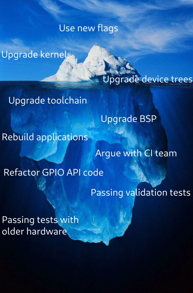
(and here it also begins the never-ending story of upgrading the kernel to 6.6+,
which I will summarize with the following image)

All my fiddling with the PLL settings could have broken something a bit subtle. Indeed, the exposure setting was havoc.
But it wasn't easy to notice, at first, because you know... you have a thousand different problems to address, and if the image is darker when the slider is left, and is lighter when the slider is right, then engineering rule number one wants to kick in, and it mostly works. Unless, you actually spend some time measuring it. (or a photographer with proper knoweledge of cameras, lenses, and measuring tools, enters the show, but that's our external consultant, and he has a habit of asking for expensive money)
So I had to come up with some smart technique to measure the exposure.
I found a guy online who wanted to measure the line offset of a rolling shutter sensor, like mine.
The experiment works like this: you pulse a led, directing its light on every pixel of the sensor, and, depending on the height of the stripe that is captured, you can estimate exposure time, or line offset, if you know one or the other, by using this formula:
n = (t_led + t_e) / offset

Theoretically, I knew the line offset, because I think that it is written in the sensor's datasheet (but instructions were a bit unclear, as always... why did I choose this job, anyhow? do you remember??) So practically I couldn't get any meaningful or reproducible result using this method.
Also, you can't really tell, if you don't zoom into the picture, but the edges of those orizontal stripes aren't actually very well defined - and that's understandable, since lines at the edge get less amount of light compared to the ones in the middle - but this also means that it is difficult to assert when a line is lit and when it is not, which means that you can just use this data to forge the measure to be whatever you want.
Note that this could also be because of what I discovered by doing the next experiment, but I didn't double check after that.
So I went to the outback of our warehouse and took
this old beast
out of the dust.
No, all the other scopes that we have, are digital ones.
This experiment works like this:
But when captured using the camera, instead, it looks like this:
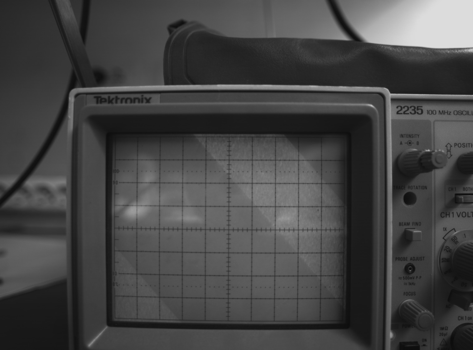
The larger the stripe, the longer the exposure, and... you can basically read the exposure time directly on the oscilloscope grid!
exposure time = stripe width
This got me exposure times about 2.14x the theoretical ones. What is 2.14? Well, it is exactly 1728 / 804, which is the frequency of the PLL I played with.
I love when, in the end, these experiments turn out so smooth!
 (I am a simple man)
To be fair, even this wasn't 100% an idea of my own, but I took inspiration from
this.
So I did a quick fix to compensate for it, and the new camera is finally ready to go!
In the mean time, also the usual boring stuff needed to be done: keep an eye to maintain backward compatibility with older cameras, check with older protocols, validate special applications, handle different Bayer matrices, and so on... and also pay attention to the necessities of the production line.
Overall, this took months, and everything is working very smoothly in the end. A big thank you to all my colleagues: this wouldn't have been possible without our conjoined efforts. Also kudos to the AI-team, they teach machines things that I can only dream of!
Code available on demand.